

In the real world and in optical simulation, a ray represents the path followed by optical energy. A ray propagates until it encounters:
- a surface boundary,
- an inhomogeneity in the medium,
- or a participating volume such as pigments, particles, fibers, or voids.
At each interaction, physical optics laws determine how the ray’s energy is redistributed between reflection, refraction, absorption, and scattering.
Because energy redistribution occurs at every interaction, light transport must be modeled as a sequence of physically governed events.
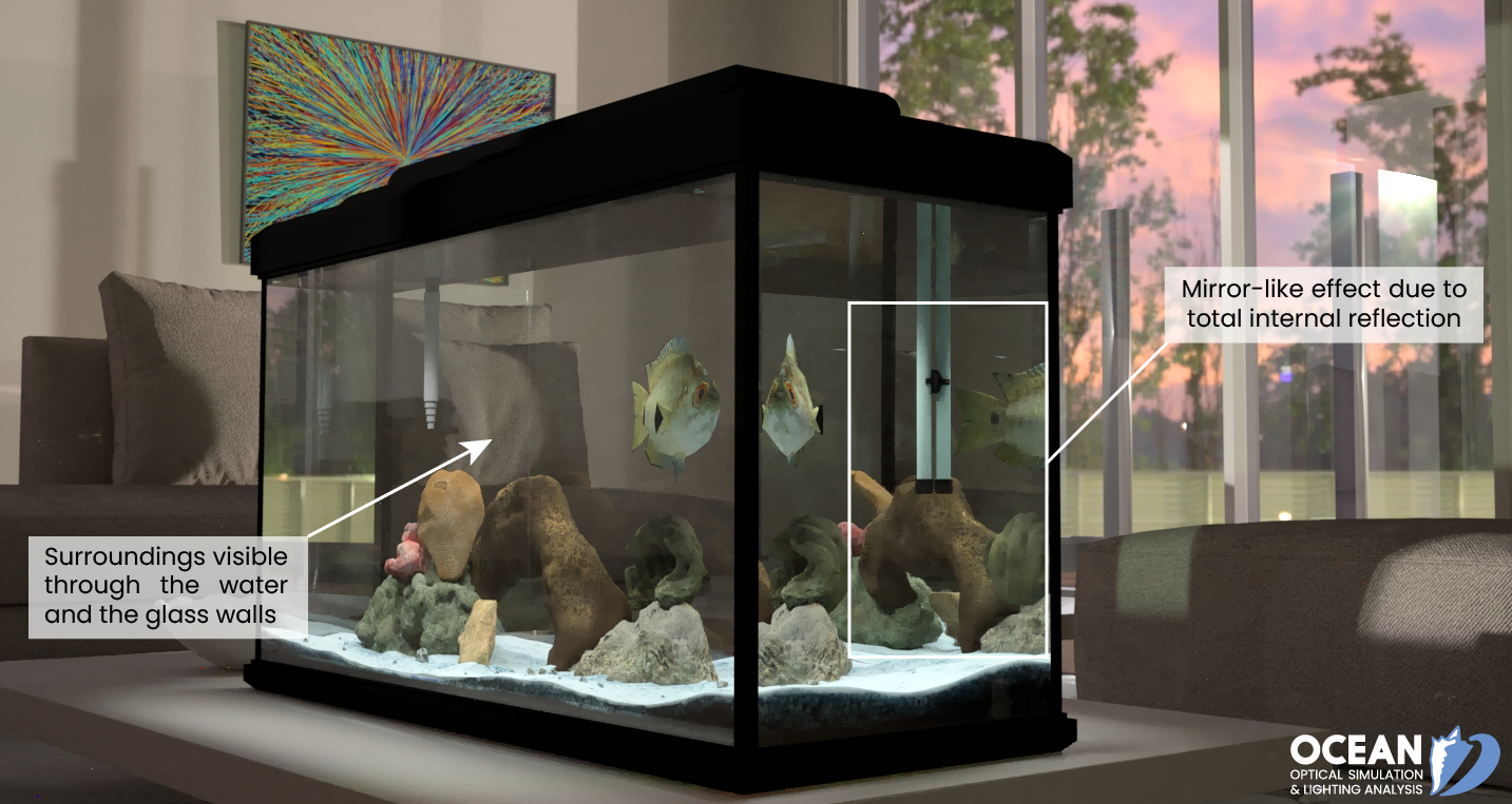
Looking at the fish tank as shown, we can see the same fish in two different locations, because light changes directions when it passes from water to air.
In this case, the light can reach the observer by two different paths, and so the fish seems to be in two different places. This bending of light is called refraction and is responsible for many optical phenomena.

Why does light change direction when passing from one material (medium) to another? It is because light changes speed when going from one material to another. The speed of light depends strongly on the type of material, since its interaction with different atoms, crystal lattices, and other substructures varies.
We define the index of refraction n of a material as:

where v is the observed speed of light in the material and it is wavelength dependent. c ≈ 3.00 x 10⁸ m/s -speed of light in a vacuum.
Since the speed of light is always less than c in matter and equals c only in a vacuum, the index of refraction is always greater than or equal to one for visible spectrum.
The refractive index quantifies how fast light propagates in a material compared to vacuum. It is defined as the ratio between the speed of light in vacuum and its phase velocity in the medium.


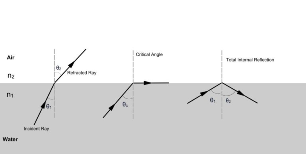
The refraction of light when it passes from a fast medium to a slow medium bends the light ray toward the normal to the boundary between the two media. The amount of bending depends on the indices of refraction of the two media and is described quantitatively by Snell’s Law.
Why this matters:
Because the refractive index depends on wavelength, refraction is inherently spectral. Dispersion effects cannot be reproduced without wavelength-resolved data.

Because refractive index varies with wavelength, each spectral component of light refracts differently. This phenomenon, known as dispersion, is responsible for:
- chromatic aberration,
- wavelength-dependent caustics,
- angular color shifts in transparent and translucent materials.
Read more in our article: https://eclat-digital.com/spectral-rendering
Common misconception: Dispersion is a secondary effect.
Reality: Dispersion directly follows from the wavelength dependence of refractive index.


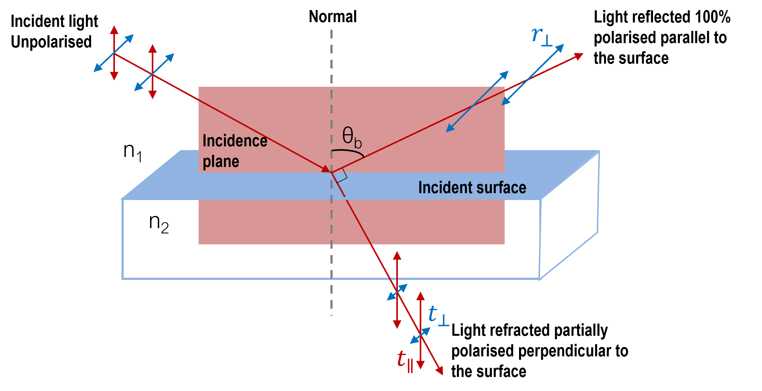
When light falls on the interface, part of it is reflected and the rest is transmitted. The distribution of the light’s energy on the interface between the two media can be calculated with Fresnel equations. That is, they give the reflection and transmission coefficients for waves parallel and perpendicular to the plane of incidence (Figure below). This shows that considering polarization of light in simulation calculation is important for physical accuracy. For a dielectric isotropic medium in Ocean™ Fresnel equations dictate the probability of the light reflection or transmission governing how many rays following these paths resulting in power distribution of the physically true light-material interaction for a ray-tracing algorithm.

The amount of polarization depends on the indices of refraction of the media involved.
Unpolarized light has equal amounts of vertical and horizontal polarization. After interaction with a surface, the vertical components are preferentially absorbed or refracted, leaving the reflected light more horizontally polarized (in ![]() symbol
symbol ![]() refers to polarization perpendicular to the plane of incidence).
refers to polarization perpendicular to the plane of incidence).
Why this matters:
Because Fresnel coefficients differ for each polarization state, ignoring polarization leads to incorrect energy distribution at interfaces.
Fresnel equations quantify how incident electromagnetic energy is split between reflection and transmission as a function of incidence angle, polarization, and refractive indices.
It defines the reflection coefficients as:

And the transmission coefficients as:

Note that these coefficients are fractional amplitudes, and must be squared to get fractional intensities for reflection and transmission.

Checking out conservation of energy in this situation leads to the relationship:

which applies to both the parallel and perpendicular cases (both polarization states).
The angular dependence of Fresnel reflectance produces characteristic polarization effects.
 Typical reflection and transmission curves for external reflection. These curves are the graphical representation of the Fresnel equations. Note that the reflected amplitude for the light polarized parallel to the incident plane is zero for a specific angle called the Brewster angle.
The reflected light is then linearly polarized in a plane perpendicular to the incident plane. This polarization by reflection is exploited in numerous optical devices.
 Polarization by reflection.
It can be shown that reflected light is completely polarized at an angle of reflection θb, given by Brewster’s law:

At this angle, the reflected light becomes fully linearly polarized perpendicular to the plane of incidence. This effect is widely exploited in optical devices and must be reproduced accurately in physically based simulations.
Fresnel equations can also be applied to absorbing media, including metals. In that case, a complex refractive index needs to be used [Read Complex Fresnel interface law in Ocean™ documentation]
A complex refractive index is used to quantify not only the phase change per unit length (ratio of the phase velocity of the wave to the speed of light) but also (via its imaginary part) propagation losses (e.g. caused by absorption and scattering). [Read Complex dielectric function in Ocean™ documentation]

Where:
- n0 is the “standard” refractive index
- κ is the optical extinction coefficient
- and both are wavelength dependent.
The optical extinction coefficient “indicates the amount of attenuation when the electromagnetic wave propagates through the material”. The larger the value, the more light is absorbed and scattered by the material. This characteristic is dimensionless. It is related to the absorption coefficient ![]() through
through

This value quantifies how much light is absorbed per unit distance as it propagates through the material and has a dimension ![]() .
.
Because absorption accumulates along optical paths, interface physics and volumetric attenuation cannot be decoupled.
As light propagates through an absorbing medium, its intensity decreases exponentially with distance according to the Bouguer–Lambert law.
In the figure below, the absorption along a path (x0; x) is ruled by the Bouguer-Lambertian law, giving the resulting intensity after a distance d:
![]()
 All above described values are wavelength dependent so the spectral information about incident light and its interaction with the media are strongly dependent on spectral data.
Participating media contain particles or structures that interact with light throughout the volume. Examples include:
- pigmented polymers,
- hazy glass,
- coatings with fillers or flakes,
- biological tissues,
- atmospheric media.
In such real-world materials, light undergoes multiple scattering events before exiting the medium, that have an impact on the appearance of the final object.
When particle sizes are comparable to the wavelength of light, scattering behavior is accurately described by Mie theory. The angular distribution of scattered light depends strongly on:
- particle diameter,
- refractive index contrast,
- wavelength.
This leads to effects such as forward scattering, haze, and reduced contrast. [Read more about Mie medium in Ocean™ documentation]

To efficiently model volumetric scattering in complex scenes, phase functions are used to describe the angular redistribution of light after a scattering event.
A commonly used model is the Henyey–Greenstein phase function, which allows continuous control over scattering anisotropy and can be applied spectrally.
Because scattering directionality affects path length and energy loss, volumetric models directly influence color build-up and brightness.

Responses